
I asked a while ago, how to build an automatic light switch and finally got around to actually building it.
My board is an ESP8266 mini D, and ignoring all the sensor parts, my problem right now is powering the actual light.
It’s just a small LED array and I connected it directly to the 5V and GND pins (controlled via a transistor).
Measuring from the wall (so including the PSU), this whole setup pulls about 3W (so far expected), however, one small component close to the USB connector gets uncomfortably warm, and I’m not sure, whether that’s ok.
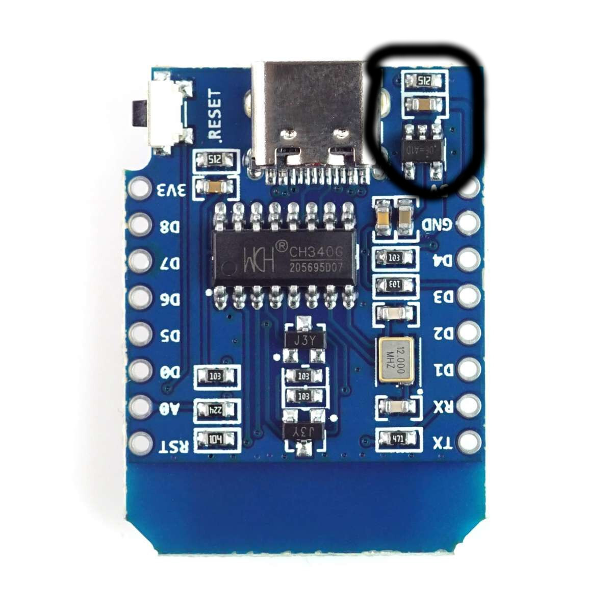
The hot component is one of the two small thingies circled in the picture. I thought the 5V get pulled directly from the USB plug, so I’m not sure, why there is any circuitry involved.
I have never used an ESP but as far as I can tell, you are right. There is no component involved for the 5V. Some boards have a diode and a fuse between VBUS (5V USB) and the 5V rail on the board, but that is not the case for the board in your picture.
The black component with “512” is just a pull-down resistor for one of the CC lines of the USB connector. This should not get particularly warm.
The brownish thing is the input capacitor of the voltage regulator. It can get a little warm due to ripple currents, but I wouldn’t expect a lot of heat.
Are you sure it is not the black 5-pin voltage regulator for the ESP? As far as I know those ESPs can be a bit power hungry depending on what you have enabled (e.g. WiFi).
Maybe you can check the temperature without your LED matrix connected and see if it is hot as well.