I am wondering if manual inspection is the way to go for pt2? Seems almost achievable with some formatting. Anyone been down this road?
It is definitely possible to do it programmatically but like most people including me simply did it manually. though I did do this:
code
#
    # we step through a proper Ripple Carry adder and check if the gate is correct for the given input.
    # first level is will start with all the initial input gates.
    # these must have XOR and AND as gates.
    marked_problem_gates = defaultdict(lambda: defaultdict(list))
    # dict of the full adder as the index and the value of what the next wires lead to.
    full_adder_dict = defaultdict(lambda: defaultdict(lambda: defaultdict(list)))
    for i in range(len(wire_states)//2):
        for (a_key,gate,b_key),output_wire in connections['x'+str(i).rjust(len(next(iter(wire_states)))-1, '0')]:
            if i == 0:
                matching_z_wire = 'z' + str(i).rjust(len(next(iter(wire_states)))-1, '0')
                # we check the first adder as it should have the correct output wire connections for a half adder type.
                if gate == 'XOR' and output_wire != matching_z_wire:
                    # for the half adder the final sum output bit should be a matching z wire.
                    marked_problem_gates[i][gate].append(((a_key,gate,b_key),output_wire))
                elif gate == 'AND' and (output_wire.startswith('z') and (output_wire[1:].isdigit())):
                    # for the half adder the carry over bit should not be a z wire.
                    marked_problem_gates[i][gate].append(((a_key,gate,b_key),output_wire))
                if output_wire in connections:
                    full_adder_dict[i][gate][output_wire].extend(connections[output_wire])
            else:
                # since the first adder is a half-adder, we only need to check the other adders to verify that their output wire is not to a z wire.
                if (output_wire.startswith('z') and (output_wire[1:].isdigit())):
                    # if the output wire is a z wire, we mark the gate as a problem.
                    marked_problem_gates[i][gate].append(((a_key,gate,b_key),output_wire))
                else:
                    # we get what the output wires to the next step in the adder would be.
                    full_adder_dict[i][gate][output_wire].extend(connections[output_wire])

    # for the next step in the full adders, we expect the carry over bit from the previous step in the adder should be have.
    #

    print(marked_problem_gates)
    print(full_adder_dict)
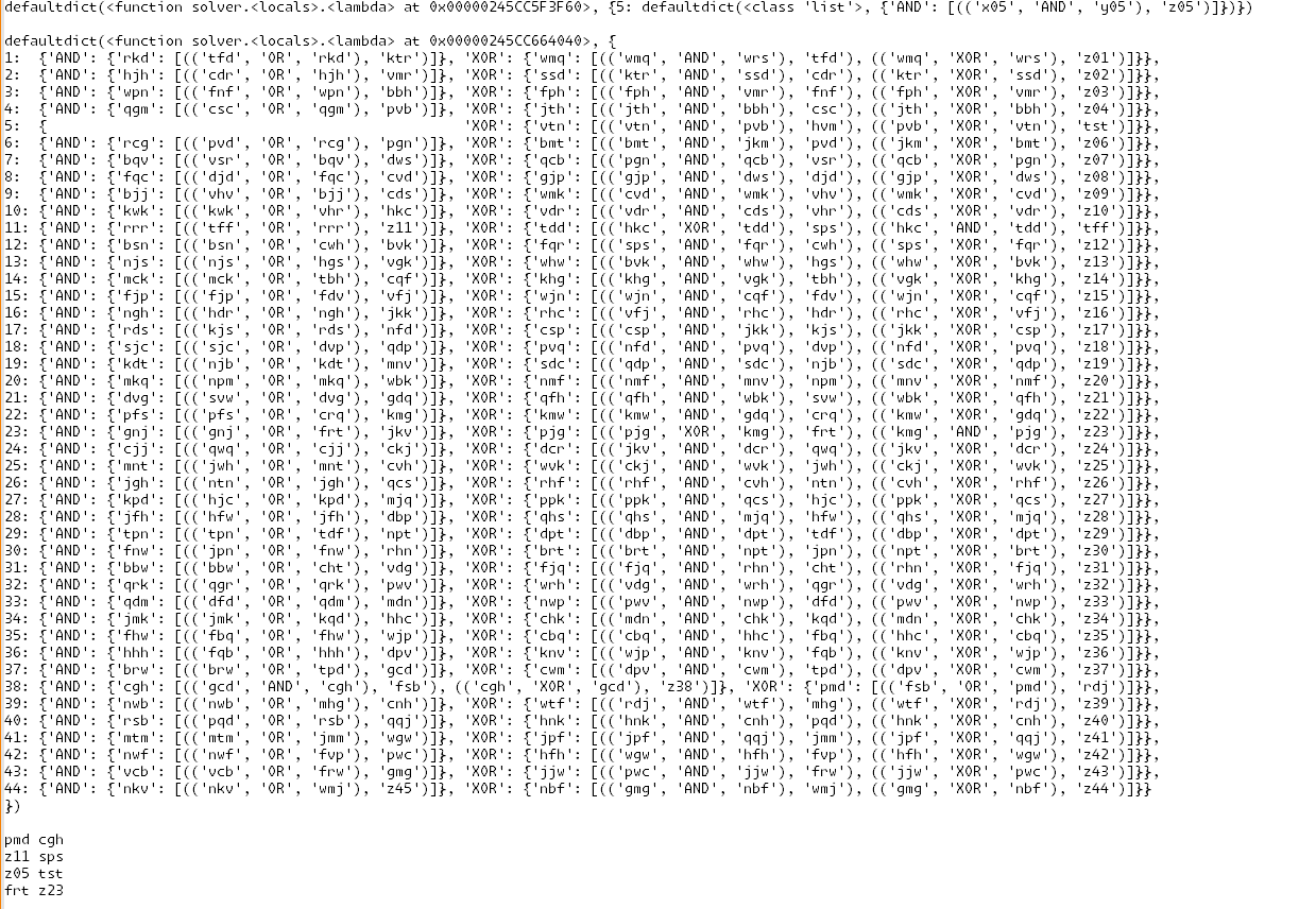
I then took the printed output and cleaned it up a little.
output

This really just me looking at it and seeing to make sure outputs are connected to the right locations. just took a minute but the highlighting of the selected work helped out. simply faster than just trying to think of some complex logic
basically bruteforce part 2 with our eyes lol
I did notice that most of the swaps where within the fulladders and not accross the entire circuit, so it was a little easier than anticipated.
I only parse each of the initial gates that the input wires to the full adders have
xandyThe only exception is that the first input wires go into a half adder and not a full adder.
So we only verify that theXORgate is connected to an output wirez00and that theANDgate does not output to azwire. EveryANDoutput wire should be connected to one logic gate and that is theORgate for the carry bit.
TheXORgate should have the output wire connected to the two gates that take in the carry bit wire from the previous adder.from there I just used my memory and intuition about full adders to clean up the output and all that to see which of the full adders have bad output wire configs.
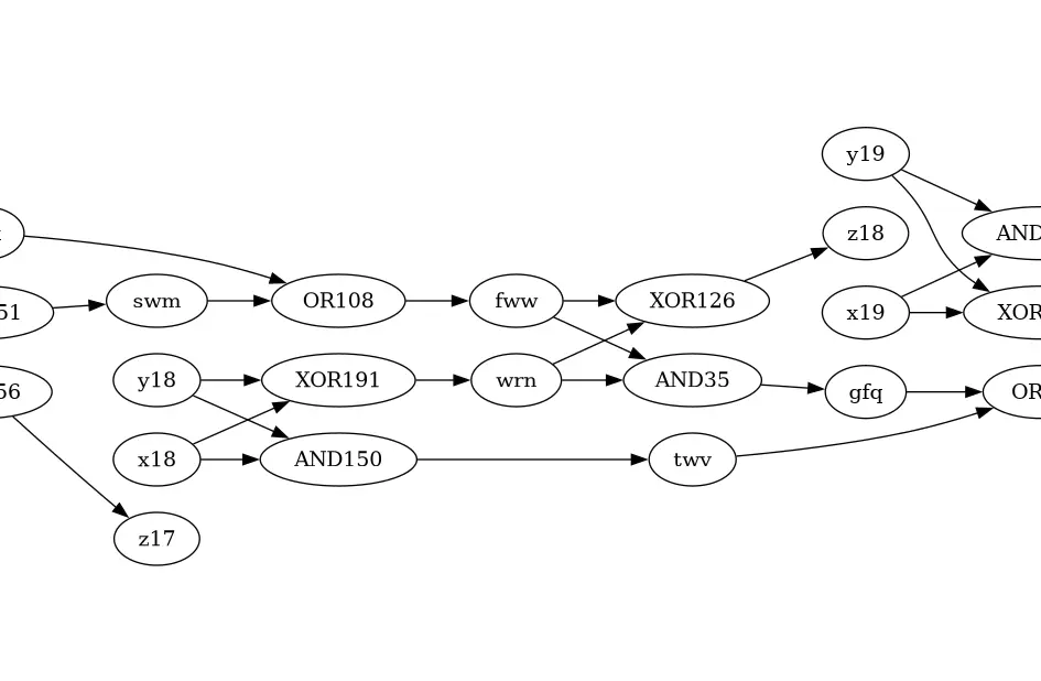
Yeah - dumped out the input into GraphViz, and then inspected it ‘by eye’ to get the swaps. Nearly finished in the top 100 in the world, too. Feels like a really bad way to get the solution, though.
If you add eg. 1111 and 1111 and expect 11110, then you’ll get an output like 11010 if there’s a mistake in “bit 2”. Can try all the swaps between x2 / y2 / z2 until you get the “right answer”, and then continue. There’s only about five different ops for each “bit” of the input, so trying all of them won’t take too long.

Feels like a really bad way to get the solution, though.
Does that come from an expectation that AoC is a programming challenge, where you typically are expected to come up with an implementation that works for all possible inputs? Because AoC is intentionally not that. Some tasks in AoC can/should be solved by hand, and I don’t think you should feel bad about it :)
I know - thank you, though, good to know it’s not just me. Not the first puzzle that I’ve solved using GraphViz, either.
Some of them do depend on some unstated property of the input that can only be discerned by inspecting it - I don’t feel too bad about that kind of ‘cheat’, as long as it goes from “the input” -> “your code” -> “the output”.
Some of them - and I’m thinking another that ludicrous “line up the hailstones” one from day 24 from last year - are the kind where you parse the input so you can output it in the right format for Wolfram Alpha. Most unsatisfying as a coding puzzle.
Im halfway through doing that, definitely feels wrong though. I’m curious to see if there is a good programatic way of doing it.
Dont you need a pair of broken bits? For mine, bit 6 is broken, because its just x6^y6. So I need to find where the carry bit got swapped to. Or are you suggesting that I swap my bit 6 operation with every other operation until it resolves?
In my input (and I suppose in everyone else’s too) the swaps only occurred within the adder subcircuit for a single bit. In general, however, the way the problem is phrased, any two outputs can be swapped, which can lead to two broken bits per swap (but this just doesn’t happen).
Mine definitely had outputs swapped between adders,
z06was justx06 XOR y06. The circuit was completely broken there.
Every “pair” of bits has the same pattern of AND and XOR, and the previous “carry bit” is passed into the same OR / (XOR + AND) combo to produce an output bit and the next “carry bit”. The “whole chain” is nearly right - otherwise your 44 bit inputs wouldn’t give a 45 bit output - it’s just a few are swapped over. (In my case, anyway - haven’t seen any others.) All my swaps were either in the “same column” of GraphViz output, or the next column.
So, yeah. Either “random swaps” with “nearby” outputs, because it’s nearly right and you don’t need to check further away; or use the fact that this is the well-known pattern for adding two numbers in a CPU’s ALU to generate the “correct” sequence, identify which ones are wrong, and output them in alphabetical order… The answer you need doesn’t even require you to pair them up.
I also solved part2 manually today, by outputting the correct addition and program output in binary and then reversing the path for all wrong outputs.
Then I just had to compare that to the formulas for a full adder and I found my swaps pretty quickly that way.
I did all of this in Kotlin and on paper, with a handy helper method to construct the paths.
It’s at the very bottom of this file on Github.
I suspect that comparing the bits and then comparing the paths to the full adder formulas can also be done ‘automatically’ decently easily, but I was too lazy to implement that today.
Yeah, same here. Graphviz to get an overview (although I didn’t actually need it in the end), plus some helper functions. I’ve got an idea for how to do it in code, though, when I get a moment.
If you get it working, would love to see it.
Posted (in the daily thread)! I was initially considering brute force on outputs which are dependencies of the first incorrect bit (but not earlier bits), but in the end I just coded up the checks I was doing by hand.


