
Since I never understood op-amps from reading or practicing problems I wanted to build a circuit to probe around and use different resistor values to set the amplification.
Currently I am attempting to build an LM358 Non-Inverting Op Amp. I am using my power supply for a +/- 12V rail, and my Arduino Uno for my 5V supply at the V+ input pin. I have chosen two 1k resistors to amplify the signal to 10V at the output and put and led as a indication that the circuit is working.
My questions are as follows:
- Is the ground for the voltage rail and input signal the same?
- What exactly is wrong with the circuit I built? I want the LED to only turn on when 5V is supplied at the input, right now the LED can turn on if I connect the ground to the voltage rail supply even without an input voltage.
- I’ve seen the post on Adafruit with the feedback resistors connected to the same ground as the rail supply, but the circuit diagram does not show where the input voltage ground is? Link: https://blog.adafruit.com/2012/06/13/ask-an-educator-making-a-non-inverting-op-amp-circuit-on-a-breadboard/
Is the ground for the voltage rail and input signal the same?
Yep.
What exactly is wrong with the circuit I built? I want the LED to only turn on when 5V is supplied at the input, right now the LED can turn on if I connect the ground to the voltage rail supply even without an input voltage.
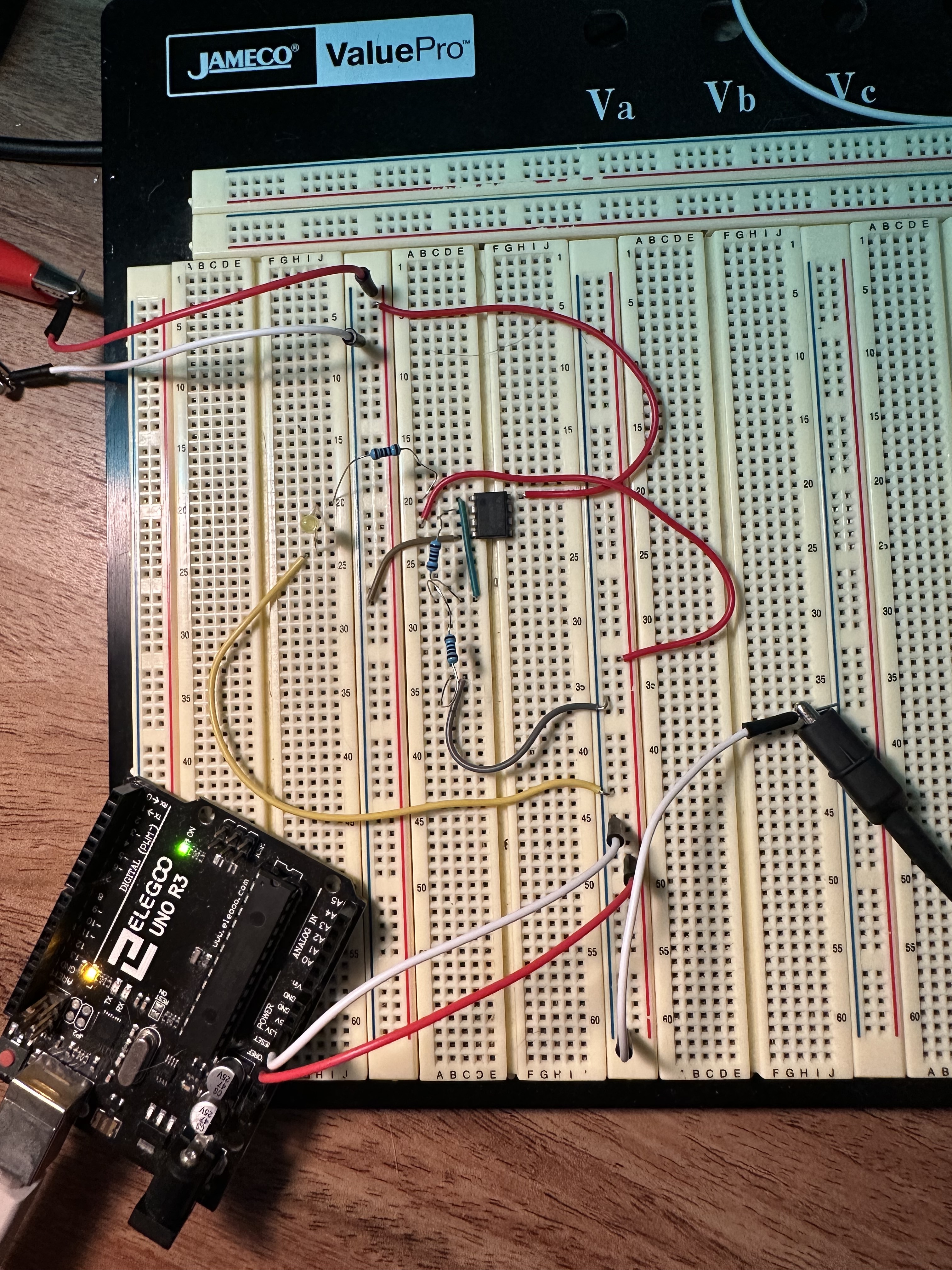
Schematic of exactly what you did… not what was on paper, how it is on the breadboard.
I’ve seen the post on Adafruit with the feedback resistors connected to the same ground as the rail supply, but the circuit diagram does not show where the input voltage ground is? Link: https://blog.adafruit.com/2012/06/13/ask-an-educator-making-a-non-inverting-op-amp-circuit-on-a-breadboard/
It’s the same as the opamp’s ground.
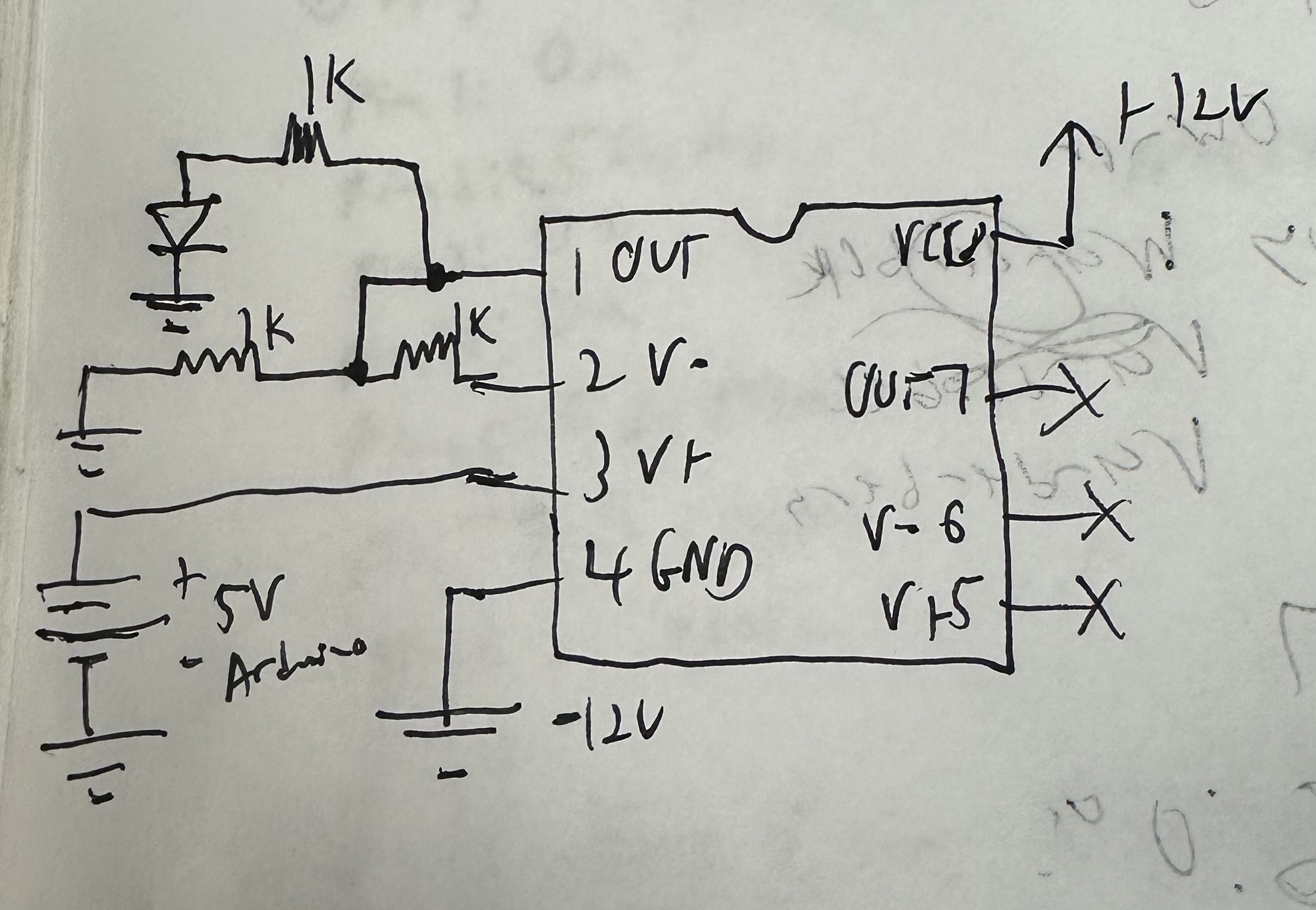 Here’s a schematic representation of what I built on the breadboard, establishing the same ground point works but the LED still turns on even when V+ is disconnected from the 5V Arduino pin.
Use a single power suppy (GND and +12V) and tie the Arduino’s GND with that GND.
Your circuit fails because the Arduino’s GND is tied to the -12V from the dual power supply, so the +5V that the Arduino outputs equal to -7V on the non-inverting input. Since this is a non-invering schematic, the opamp doesn’t invert the signal. Instead, it tries to double the -7V to get -14 on the Out, but since you’re powering the opamp with -12V, it can’t achieve a voltage that low, so it outputs the maximum it can give: -12V.
The LED turning on even when there’s no signal on the non-inverting input is probably a floating input problem. It picks up EMI so it just amplifies that. Try connecting the non-inverting input to GND, the LED should turn off… that or you burnt one of the opamps, lol, try the other one in the package.
I tied the Arduino’s GND to the power supply GND, the output is still 10V, tried different ICs as well, not really sure what the issue is at this point. Tying the non inverting input pin to ground does turn OFF the LED, but the led stays on regardless if the 5V is coming from the arduino or not, it seems that the op amp outputs 10V regardless of the non-inverting pin, however if I use different resistors to lower the gain or change the input voltage to 3.3V instead of 5V, I do get the output voltage. I just don’t understand how there can be 10V at the output with no voltage from the inverting or non-inverting pin.
Well, you should get 10V. You input 5V, the voltage gain is 2, so the output should be 10V. I don’t see a problem here, the circuit is working as expected.
But that’s the thing, it outputs 10V even when the 5V rail from Arduino is disconnected at V+ (pin 3).
Put a pot between the arduino’s +5V and the circuit, see what happens when you turn it. A 10K to 100K pot should be enough.
the first thing i’d do is connect the GND from your arduino and from your power supply. At the moment there does not seem to be a common ground or it is off picture.
The circuit works when there is a common ground (makes sense ofc but originally I thought they had to be separate), I didn’t want to put 5V and 12V on the same rail of the breadboard. Now what I find strange is that even without the 5V input voltage, I still get 10V at the output of the Op-amp which is very confusing.
Just a word of caution - education is a process of diminishing deception. Books provide a simplified version of real World electronics. Universities and colleges put a lot of effort into designing lab practicals that will actually work and give the predictable results that students expect.
So the normal learning process when it comes to op amps - is to read and understand the theory. Then complete those crafted lab practical exercises - having been introduced to the added complication of systemic and random errors. Then do your own thing, when all the remaining Real Life complications hit you like a brick.
So, if you can find a course in analogue electronics, even a distance learning one, you might find the steps are smaller and more easy to assimilate.
I understand your caution, however I understand the theory behind OP-Amps, theory can only go so far which is why I’m building a circuit on a breadboard now. I should clarify that the basic rules for ideal op-amps I have a grasp of, although I can never seem to remember these rules. For example, I have the formulas for a BJT and MOSFET transistors memorized because I spent a lot of time reading and using them in practical applications. Op-amps I have spent a lot of time reading but no time building circuits, which is essentially what I am trying to do now. I have a degree in EE, and at this point this is one of the basic components that wasn’t covered much in university, nor did reading or doing practice problems help. I’m very much a hands on learner, I can read formulas and equations all day but if I don’t apply what I learned I’ll forget it after several days unless I repeatedly practice.
What worked for me, that may not do so for anyone else - is to take an existing circuit (usually a reference one provided by a manufacturer) and build that. Get that working (sometimes, it hasn’t worked- the manufacturer’s technical support department has often been very helpful, especially when their reference design has a design fault or has been misprinted - after doing that, they used to send me unmarked, pre-production chips/etc to play with and provide feedback).
Then modified that design, to test my understanding. Tried different board layouts, guard rings, etc and documented the effect. When it didn’t work as expected - took that back to their tech support to see if we could work out why.
So, for me, taking something that works and keep modifying it, just a little.
I recommend EEVBlog’s OpAmp tutorial. His explanation is pretty simple to understand. Basically there are two rules (note these rules are ideal, but the exceptions can usually be ignored):
- No current flows into the inverting and non-inverting inputs.
- For negative and positive feedback circuits, the OpAmp wants to keep the inputs the same by changing its output, and will sink power to its positive or negative power rails to achieve this.
