

I tried adding an AUX jack to a car stereo with an internal CD player and no native support for one.
When I first did tests, simply attaching to one of the amp’s input lines while the stereo was at min volume (1, not 0, more on this later) worked wonderfully.
To install the jack itself however, I thought that it may be dangerous to have the stereo send current to the AUX device and vice versa, so I thought about installing a switch to cut the stereo’s audio input lines when using the jack and vice versa.
I thought about just muting the stereo, or turning the volume to 0, or using a dummy paused CD, but all of the three activate the mute line on the amp, which isn’t a simple binary on/off deal, and activating it would also mute the jack.
Image
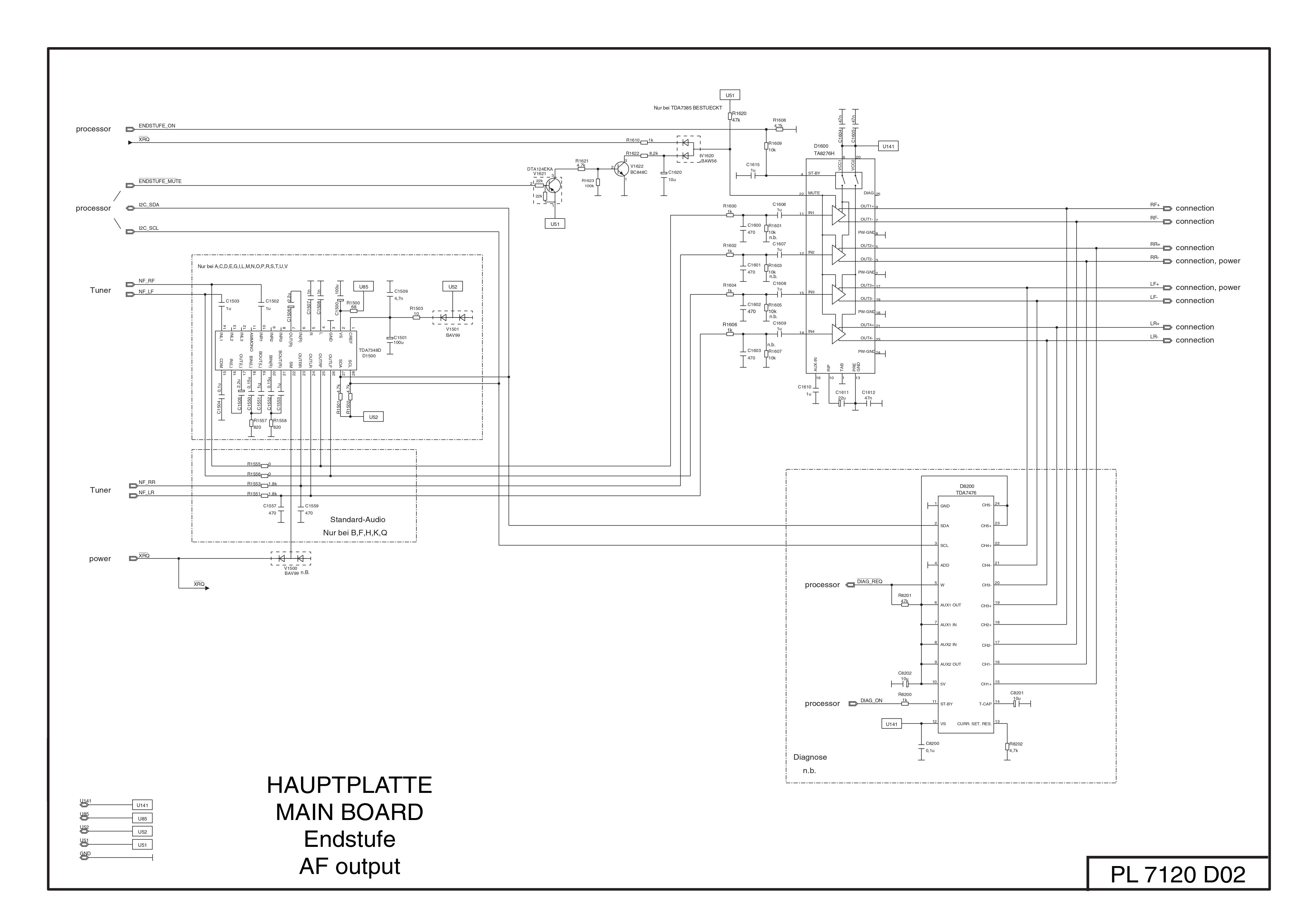
This is the original schematic of the amp circuit: Image
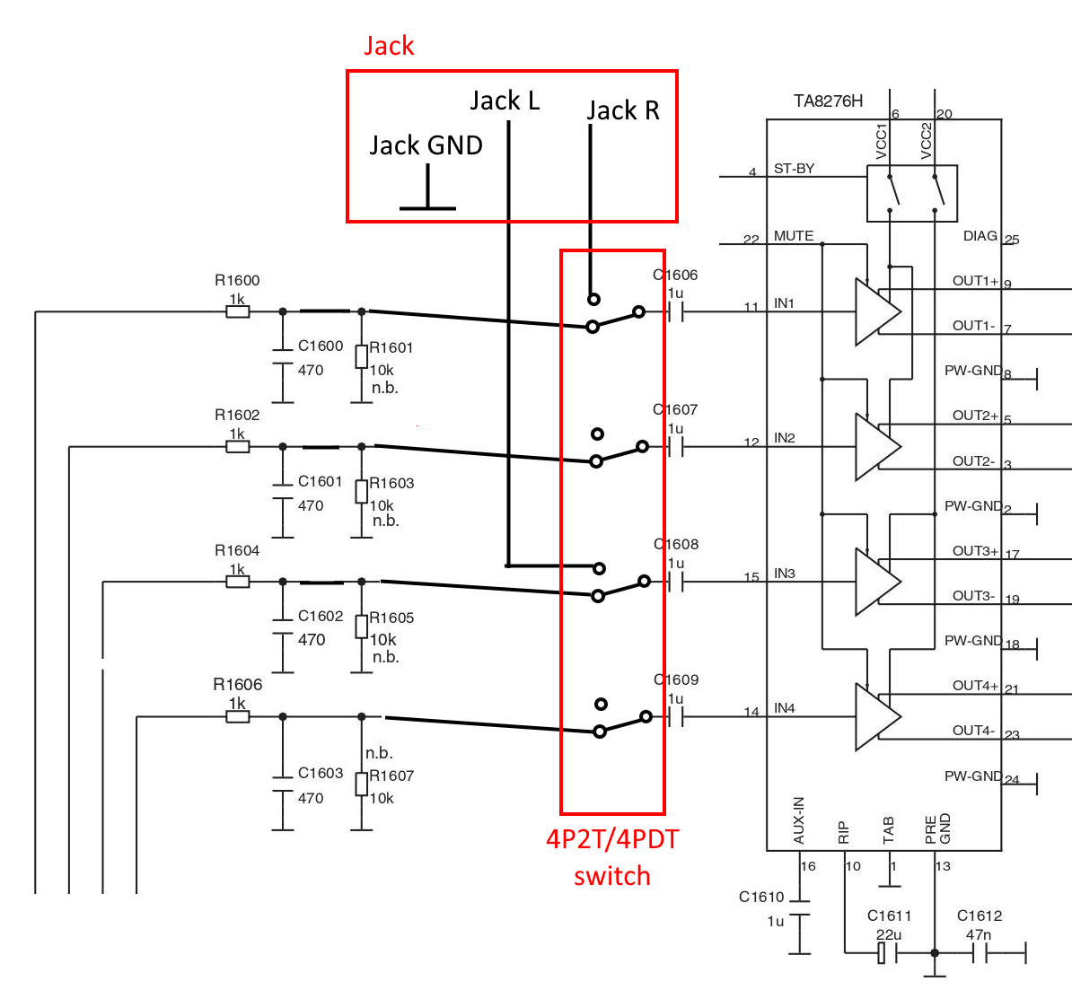
I attached to the IN1-4 lines like this: Image
I left the rear channels disconnected because a friend of mine suggested jumping two input lines could cause issues to the amp
However, once all was done, it wasn’t working correctly. First of all, when I flip the switch, some signal from the stereo still gets through. It’s very faint and you have to turn the volume way up to hear it, but it’s there. This concerns me if it may lead to damage to either the plugged in device or the stereo, and if it could be the cause of the following issue.
Second, when a male to male cable is plugged in the other end (without even anything attached to the other end), a high pitched whine starts playing from the speakers. I tried bypassing the jack with alligator clips to the rear terminals, but it still happens, and when this happens I suddenly read a resistance of 7~8MΩ between either of the jack’s channels and ground. I haven’t tried another cable, but if I test the cable itself when it’s unplugged I can’t read anything between the rings.
I’m especially puzzled as to why there were no issues when I tried by tapping into the lines, but now that I did it “”“properly”“” (at least in my head) it’s problematic.
The full schematic for the stereo can be found by googling “BLAUPUNKT FIAT B-MPV CD-MP3 7645324316 SM”
When I did this a long time ago, I simply connected the aux input parallel to the CD player audio out lines, To use the aux, flip a CD upside down. Still works to this day.
I read about that, but it seems that the internal disc drive transmits digital data all the way until the main processor (or whatever connects to the amp input).
I’m puzzled - you describe wanting to add a headphone jack (eg an output jack socket into which headphones can be plugged) - yet you seem to actually want a socket that provides auxiliary input.
However, if you are indeed trying to add external input and are disconnecting the inputs to an amplifier - you might want to tie those disconnected inputs to ground.
My bad - yes I mean an AUX input I thought I would’ve needed to ground the unused lines (not sure if I should connect to ground directly or with a resistor) - you think that could be the cause of the whine? The whine comes from the front speakers too. And I really can’t understand how and why I can still get some signal from the stereo…
It’s usually a good idea to look at what’s normally connected, when breaking a circuit, and replicate that. Which I seem to remember is a 10k resistor with a parallel capacitor (being too lazy to go back and look again). You could try the same combination, in place of the added input cable, on the lines that you plan to use and see if it whines. If not, add the cable(s) and try again. That may stop it happening on all channels.
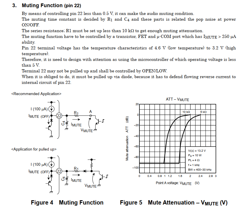
There are two muting methods - open circuit the input (via a switch or a gate) - in which case there will probably still be some signal transfer through capacitive coupling - especially if the amp side of the open circuit is high gain. Or short the signal path to ground - and that short will have some impedance and thus the signal is only attenuated and not removed all together.
Turning the amp gain to far higher than it ever would be in practice is hardly a fair test. There aren’t many amps that will be noise free under those conditions - and, in this case, there will be a signal to amplify, albeit highly attenuated.
It’s good to be cautious - cascade failure can be waiting to bite. Never direct connect unless unavoidable - add a series capacitor, if you can. Yes, not usually a good idea to provide a dc path unless essential and, even then, current limit it if possible.
It’s usually a good idea to look at what’s normally connected, when breaking a circuit, and replicate that. Which I seem to remember is a 10k resistor with a parallel capacitor (being too lazy to go back and look again).
There’s a resistor, then parallel capacitor and resistor to ground, and finally a capacitor to the amp. I could try replicating the parallel pair if that could help
add a series capacitor, if you can.
Would that be a polarised capacitor for protection? And on both the original and my added lines?
That sounds reasonable. That capacitor to ground may be needed for stability - lack of it could explain the problems that you have been experiencing.
Unless you are providing a bias voltage on the external input, a non-polarised capacitor is a better bet.
That sounds reasonable. That capacitor to ground may be needed for stability - lack of it could explain the problems that you have been experiencing.
Unless you are providing a bias voltage on the external input, a non-polarised capacitor is a better bet.
The way I modified the circuit, the AUX goes into the .2μF capacitors that was already there before the amp input lines, is that sufficient?
Sounds good to me (pun intended)…