- 21 Posts
- 9 Comments


Probiers doch mal mit improv theater, stand up comedey…angeln, magnet angeln, schach, programieren…es gibt so so viele dinge die nur zeit und kaum geld kosten
huch eine wiederhohlung das heißt sie ändern etwas an der matrix… Schön das ihr noch da seit
Freizeit und Urlaub ist nicht das selbe.
sowas sind die seiteneffekte von zu lange nich online gewesen, fehler wurde behoben
Schön zu sehen das ihr alle noch da seit :D

 2·2 months ago

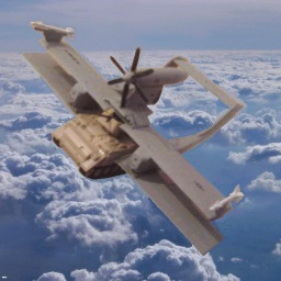
IR homing sensors before the digital age where a piece of analog signalpath art. Its mostly rotating a singular ir sensor in 45degree and then mapping the inputs rotation compensated to the control surfaces. Simple at core but cant tell the difference between a jet exhaust, the sun, or a flare.
Modern version are boring is a High resolution ir cam and some blackmagic AI picking targets apart from flares.
source for the information in the title: i made it up, or did i?
Naja das tuen die ADAC und Rettungs Helis gelegentlich auch…aber solange der ADSB transponder an is sieht man sie trotzdem aufm radar. Was auch immer da nachts geflogen is hatte seinen Transmitter definitiv aus