
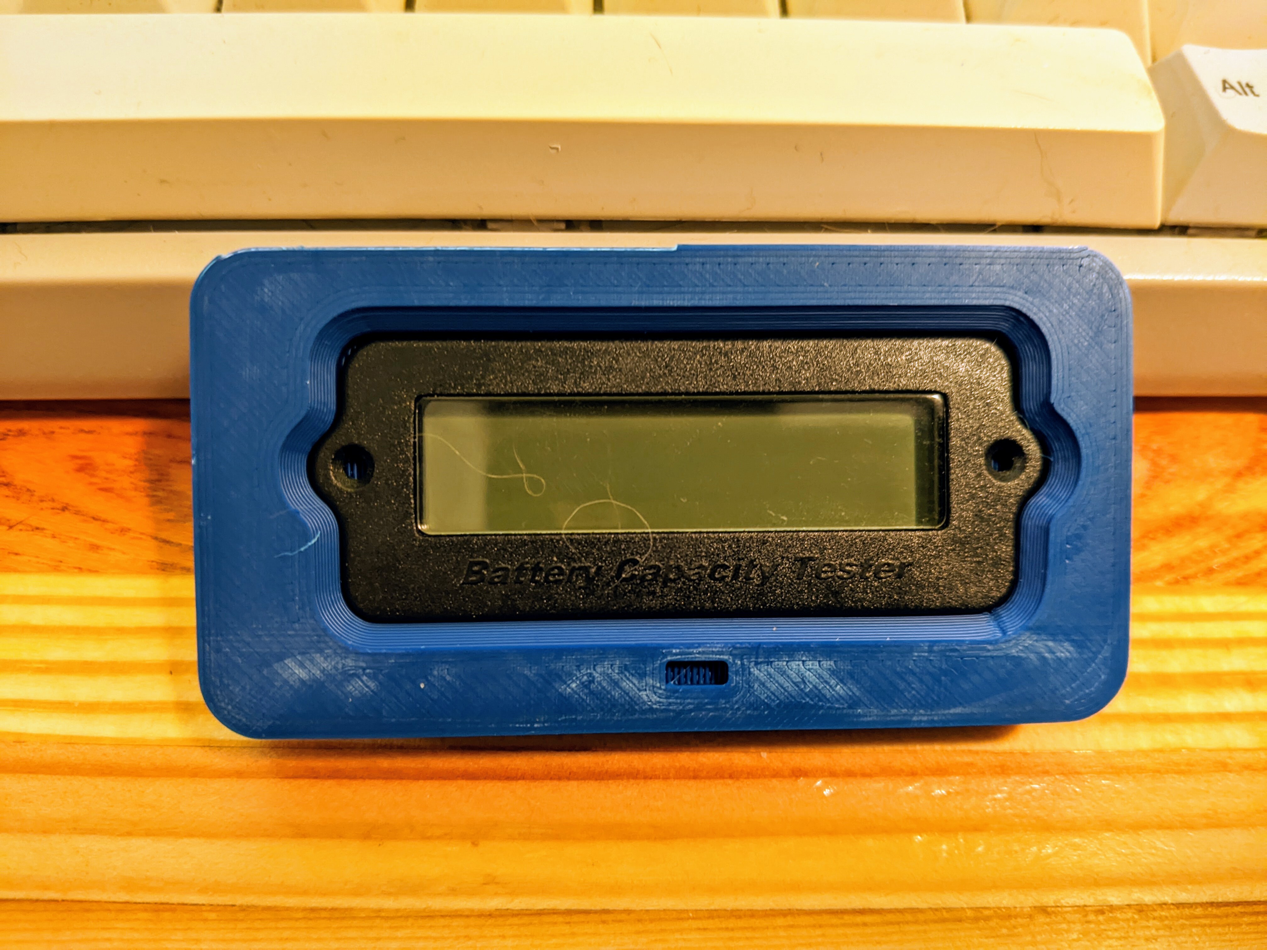
Pardon the brim remnants. Not pictured: the many prior iterations. This started as a head on photo that I imported into fusion 360 and scaled after some measuring with calipers. It’s not perfect, but it’s rapidly approaching good enough. The square indent is to help with orientation - although the part obviously is not symmetrical, it’s much harder to judge the home.
Oh wow, that is very strange. I checked if 23.22mm was anything in inches, and it’s 0.914 and change, so it’s not an imperial thing. I wonder if it just comes from people eyeballing it with no real dimensions or something?
Well, as you were I guess. ¯\_(ツ)_/¯
The mold was likely 24mm. There could be some shrinkage or a the shot of plastic was a bit light for that set.
Or, it was actually 23.22mm and the dimensions were calculated from another reference point, like PCB or LCD size. If anything, .22mm was supposed to be .25mm clearance.
Translating CAD into plastic and back into CAD can be a very strange thing sometimes.
Edit: I reverse engneer a ton of things in CAD. Sometimes just some calipers work, but for curves, pictures + calipers + gauges are the way to go. Sometimes, if you get core dimensions correct, the correct curves can “emerge” from the design itself, but that is a somewhat rare dark art. Pro-tip: A reverse engineered part is almost never going to be perfect, but almost always has the potential to be better than the original.
I appreciate the detailed reply! If anything, someone reading it will learn something. It’s always amusing trying to make nice fitting sockets for random electrical parts. Sometimes the dimensions make a lot of sense. Other times they feel very random, which is surprising given that basically all these parts are probably modeled in CAD.
I appreciate you not being defensive and just explaining your process in so much detail. I learned something about how finnicky some of these parts can be. I wonder if another strategy would be to trace the part onto paper and scan it, to get an undistorted shape?
And I don’t mind explaining things, it’s someting I sort of can’t help to be honest. I hope it’s useful to someone.
Tracing can work, but it’s a little fickle too. In this case the part had a small radius on its face. There’s also the whole pencil lead has width thing, but it can work OK if you’re very intentional at keeping the pencil tip pointing at the part in question.
Flatbed scanners also work fairly well, but they’re focused at the glass height and you quickly lose detail if the parts have a radius on them.